A Flexible Copper FPC Circuit is a thin, bendable electrical connection built on a flexible insulating film, often polyimide. Copper traces carry signals or power while the circuit bends around compact product designs. You might find one folded beneath a phone camera, routed through a printer hinge, or tucked inside a wearable device. Small space. Careful engineering.
Unlike a rigid board, an FPC must handle movement without cracking its copper or separating its layers. Designers consider copper type, trace width, coverlay, connector placement, and the circuit’s bend radius. Repeated flexing needs special attention; a circuit that bends once during assembly may not survive thousands of operating cycles. Joe Fjelstad, a recognized flexible-circuit author and industry specialist, has written extensively about flexible circuit design. A practical paraphrase of his design guidance is: “Plan for the circuit’s actual motion, not only its flat layout.” This is a paraphrase, not a verbatim quotation.
That distinction matters. A drawing can look simple while hiding stress near a connector or sharp bend. The right material stack-up depends on the application, expected movement, temperature, and manufacturing process. There is no single FPC design that fits every product. Even experienced teams may need prototypes and bend testing to uncover weak points. A useful introduction should explain what these circuits are, how copper and flexible substrates work together, where FPCs are used, and what trade-offs shape reliable designs. The details are practical, not glamorous. But they determine whether a circuit keeps working after the enclosure closes.
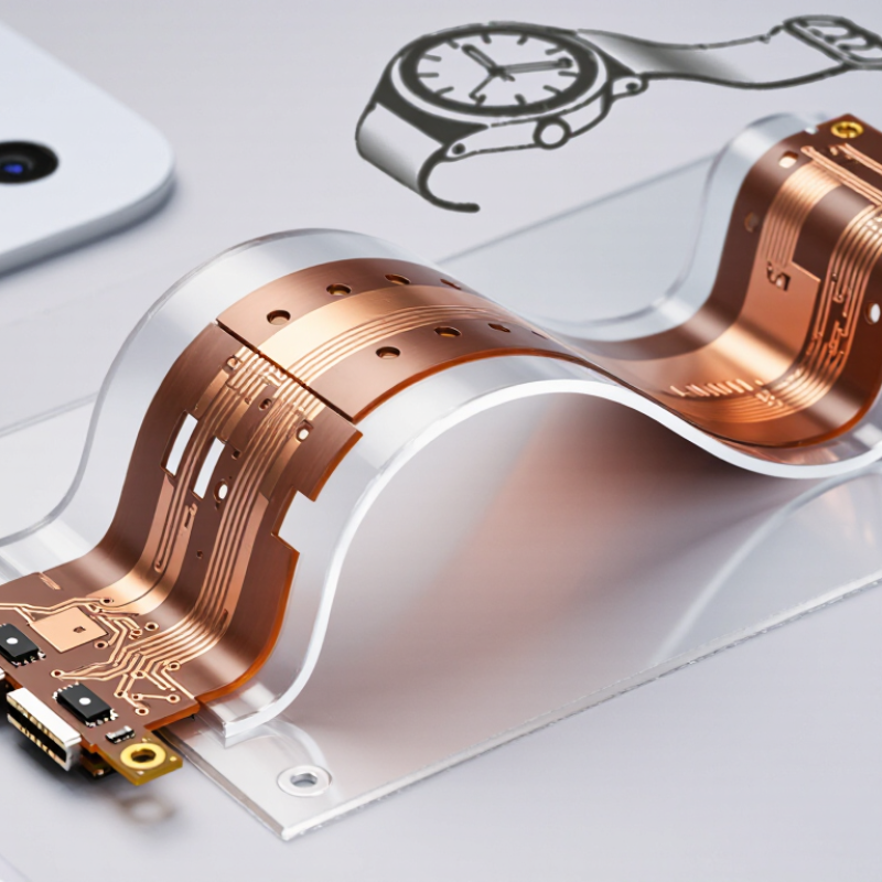
A flexible copper FPC circuit is a thin electrical circuit built on a bendable insulating film. Copper foil forms the conductive paths, while a polymer base, often polyimide, supports them. A protective coverlay usually covers the traces and leaves selected pads exposed for connection. Unlike a rigid board, an FPC can fit around a hinge, fold into a compact housing, or connect parts that move relative to each other.
Its defining characteristic is flexibility, but flexibility has limits. A circuit designed for one-time assembly bends differently from one expected to flex repeatedly. Copper thickness, layer count, bend radius, and material choice all affect durability. Sharp folds can strain copper traces; gentle curves usually reduce that stress. Thin and light construction can also save space, though it may make handling and assembly less forgiving. Small details matter.
Core performance still depends on electrical and thermal requirements. Trace width and spacing influence current capacity and signal behavior, while nearby components can restrict the bend area. In practice, that distinction is easy to overlook: a flexible circuit is not automatically suitable for every moving application. Designers typically check the intended bend path, operating conditions, and connection points before selecting a stackup. Even then, real-world movement may reveal assumptions that looked sound on paper.
A flexible printed circuit (FPC) uses conductive copper foil laminated to a flexible insulating material, commonly polyimide. Copper thickness is one design choice: thinner foil can support a more flexible circuit, while thicker foil can carry more current, depending on the design.
The chart shows approximate nominal thicknesses corresponding to common copper weights. Actual material choices and finished thicknesses vary by application and manufacturer.
A flexible copper FPC is a layered circuit built to bend without losing electrical continuity. Its stackup often pairs copper foil with a polyimide film, plus adhesive and a protective coverlay. Common commercial copper thicknesses range from about 9 to 35 micrometres; polyimide films often range from roughly 12.5 to 50 micrometres. These are typical material options, not fixed requirements. IPC-2223C, the industry design standard for flexible printed boards, stresses that bend radius, copper placement, and layer symmetry affect mechanical performance.
The structure matters most where the circuit repeatedly folds. A single-copper-layer design is thin and forgiving; multilayer designs route more signals but need careful neutral-axis control. Keep copper traces away from the outer bend surface when possible. Rounded trace corners also reduce local stress. Small details matter. Adhesive thickness can change the stack’s stiffness, while a coverlay opening can expose pads for soldering. IPC-6013 qualification guidance addresses flexible-board performance and testing, but no standard stackup fits every application. A supplier’s material data and a physical bend test should confirm the design. One imperfect assumption is that a stated bend radius guarantees long life; actual results also depend on cycle count, temperature, and how the finished part is installed.
A flexible copper FPC circuit is built by bonding thin copper foil to a flexible insulating film, often polyimide. Manufacturing starts with careful cleaning, since dust or oil can disrupt fine circuit features. A photosensitive coating is applied, then patterned through exposure and development. The exposed design guides chemical etching, which removes unwanted copper and leaves conductive traces. Small details matter.
For double-sided circuits, manufacturers may add drilled holes and copper plating to connect the layers. Openings are cut into a protective coverlay, which is aligned and laminated over the traces. The coverlay helps protect the copper while leaving pads exposed for connection. Surface finishes are then applied where needed. Alignment can be tricky, especially around narrow pads.
The finished panel is inspected for dimensions and visible defects, then electrically tested for continuity and unwanted shorts. Some designs also require bend testing. A circuit that passes electrical checks may still fail if its copper traces are bent too sharply in use. The suitable bend radius depends on materials, copper thickness, and how often the circuit moves. There is no single recipe; manufacturing choices should follow the actual operating conditions.
What Is a Flexible Copper FPC Circuit?
Electrical Operation and Mechanical Flexibility
A flexible copper FPC circuit carries electrical signals through thin copper traces bonded to an insulating film, often polyimide. Its traces work like conductive paths on a rigid circuit board, but the film can bend to fit compact spaces. Trace width, spacing, and copper thickness affect current capacity and signal performance. Under magnification, the copper paths may look like fine, carefully spaced lines. That precision matters.
Electrical reliability depends on more than the copper itself. Connectors, solder joints, and transitions to rigid boards can become weak points if the layout or assembly is poorly controlled. A circuit may fit neatly around a hinge, yet still need a stiffener near a connector. That detail is easy to overlook. Design choices should reflect the actual voltage, current, signal speed, and operating environment.
Mechanical flexibility has limits. A broad, gradual bend is usually less demanding than a sharp crease, and repeated movement can fatigue copper over time. The bend radius, copper type, layer stack, and placement of traces all influence durability. The word flexible can sound reassuring, but it does not mean damage-proof. Engineers should test the circuit in its installed shape and, where movement is expected, through realistic repeated flexing. A small routing change can sometimes make a meaningful difference.
| Dimension | Typical Description | How It Affects Operation or Flexibility |
|---|---|---|
| Basic structure | A flexible printed circuit (FPC) uses patterned copper conductors laminated to a flexible insulating film, commonly polyimide. Coverlay or another protective layer may cover the conductors. | The thin layered construction provides electrical paths while allowing the circuit to bend or fold where the design permits. |
| Copper conductor | Copper carries current and forms the circuit traces. Flexible circuits commonly use rolled-annealed copper or electrodeposited copper, selected according to the design and application. | Rolled-annealed copper is often selected for repeated bending because its grain structure can better accommodate flexing. Copper type, thickness, trace width, and bend conditions all influence durability. |
| Electrical operation | Voltage applied across a conductive path drives current through the copper traces. Insulating layers separate traces and help prevent unintended electrical contact. | Electrical performance depends on factors such as conductor dimensions, circuit length, current, insulation, and the requirements of the connected components. |
| Flexible substrate | Polyimide is a widely used flexible substrate because it can withstand elevated temperatures encountered in many circuit fabrication and assembly processes. | The substrate supports the copper pattern and allows the circuit to conform to a product’s shape, subject to the material stack-up and specified bend limits. |
| Static bending | A static bend is formed during installation or assembly and is not intended to move repeatedly in normal use. | Static applications can generally tolerate a tighter bend than dynamic applications, but the permissible radius must be established for the specific circuit construction. |
| Dynamic bending | A dynamic flex area repeatedly bends during the product’s service life, such as in a moving hinge or carriage. | Repeated movement increases mechanical stress on copper and interfaces. The bend radius, copper type and thickness, layer count, trace layout, and required cycle life should be considered together. |
| Bend radius | Bend radius is the radius of curvature of the flexed circuit. There is no single suitable value for every FPC; guidance depends on whether the bend is static or dynamic and on the complete stack-up. | A larger radius usually reduces strain on the conductors. Follow the fabricator’s design rules and avoid sharp creases or repeated bending outside designated flex areas. |
| Trace layout in flex zones | Traces in a bend area are commonly routed to reduce localized stress; smooth transitions and suitable spacing help avoid stress concentrations. | Keep components, vias, and abrupt width changes out of highly flexed regions where possible, and use the circuit designer’s or fabricator’s recommendations for the intended motion. |
| Common applications | FPCs are used in compact electronics, cameras, displays, sensors, medical equipment, and other assemblies where space, weight, or movement matters. | They can replace some wire-and-connector assemblies, reduce routing volume, and connect parts that move or occupy irregular spaces. |
| Key design checks | Confirm current and voltage requirements, conductor geometry, insulation needs, operating temperature, bend type, bend radius, and expected flex cycles. | These checks help balance electrical requirements with mechanical life. Final limits should be verified against the selected materials, stack-up, and manufacturing guidance. |
Note: Values and bend limits are design-specific. Consult the circuit manufacturer’s material and fabrication guidance for the chosen FPC stack-up and application.
Flexible copper FPC circuits use copper traces on a bendable insulating film. They fit devices where rigid boards cannot follow the available shape. Common uses include phone cameras, wearable sensors, medical instruments, and printer heads. A short flex connection can replace several wires inside a moving hinge. Space is tight. But flexibility does not mean a circuit can bend anywhere.
Design starts with the movement the circuit must withstand. A designer should check bend radius, bend direction, and how often the assembly moves. Sharp folds can strain copper and cause cracks over time. Keep traces smooth through bend zones, and avoid placing pads or components where repeated bending occurs. A hinge that moves only during assembly needs different treatment from one that opens every day.
Material thickness, copper type, and adhesive choices affect flexibility, heat handling, and signal performance. Dense circuits may need shielding or controlled trace geometry, especially for sensitive signals. Connectors also need room for secure attachment and strain relief. Testing the assembled part through realistic movement cycles can reveal problems that a flat prototype misses. It is easy to optimize for a very small footprint and regret the serviceability later. During review, I would check the actual enclosure, not only the drawing.
It uses thin copper foil bonded to a flexible insulating film, often polyimide. The copper forms conductive traces.
The film is cleaned, coated with photosensitive material, exposed, and developed. Chemical etching removes unwanted copper. Small details matter.
Manufacturers drill holes and plate them with copper. This creates electrical connections between the two sides.
It covers and protects the copper traces while leaving connection pads exposed. Aligning it around narrow pads can be tricky.
They appear in phone cameras, wearable sensors, medical instruments, and printer heads. A short flex circuit can replace wires inside a moving hinge.
Check the bend radius, direction, and number of movement cycles. Sharp folds can crack copper over time. Flexibility has limits.
Keep traces smooth through bending areas. Avoid placing pads or components where movement happens repeatedly. I would inspect the actual enclosure, not just its drawing.
Inspect its dimensions and visible surfaces, then test for continuity and unwanted shorts. Realistic movement tests can reveal problems a flat prototype misses. A small footprint may complicate repairs.
A Flexible Copper FPC Circuit is a lightweight electronic circuit built on a bendable insulating base, with copper conductors carrying electrical signals and power. Its structure typically combines a flexible substrate, patterned copper, protective cover layers, and, where needed, adhesives or stiffeners. The choice of materials and layer arrangement affects the circuit’s thickness, durability, electrical performance, and ability to bend in a specific application.
Manufacturing generally involves forming copper patterns on the substrate, adding protective layers, and finishing the circuit for assembly. In operation, the copper traces provide electrical connections while the flexible construction allows the circuit to fit compact or curved spaces. Designers must consider bending direction and radius, repeated movement, heat, electrical requirements, and how the circuit will be supported and connected. These characteristics make flexible copper circuits useful in applications where space, weight, or movement make rigid circuit boards less suitable.