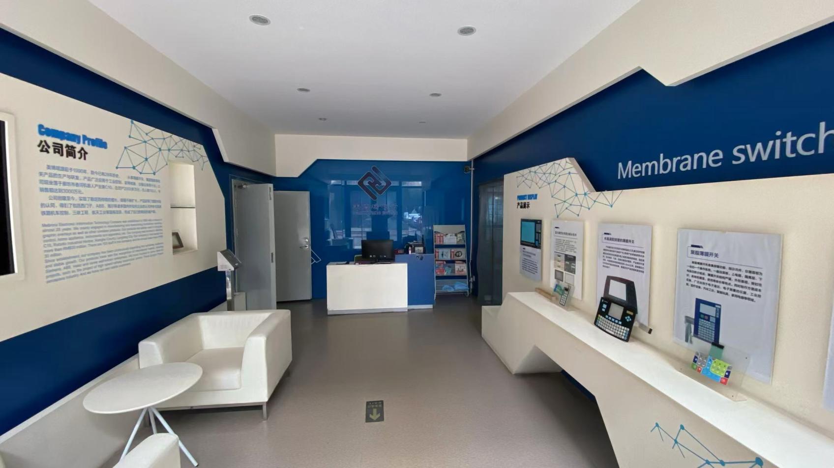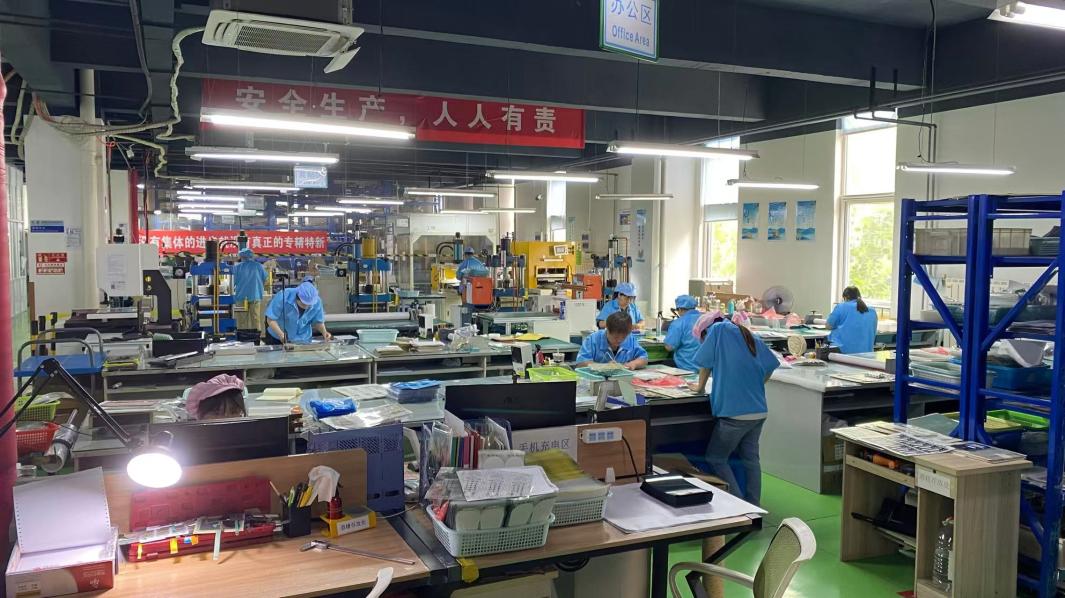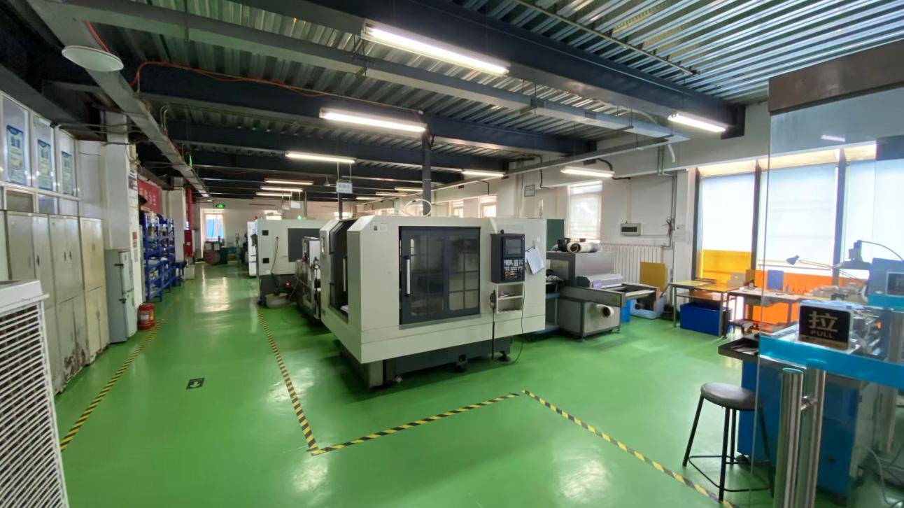
Screen Printed Membrane Circuit precision manufacturing workshop at TAVO
Laser die-cutting and precision punching for screen printed membrane circuits
Membrane circuit lamination and tactile dome assembly station
Dust-free screen printed membrane switch assembly cleanroom
Engineering Whitepaper · OEM/ODM Guide

How to Procure High-Reliability Screen Printed Membrane Circuit Assemblies: The Comprehensive Engineering, Trend & Quality Sourcing Guide

In modern industrial automation, medical diagnostics, energy grids, and transportation equipment, hardware procurement teams and embedded systems architects consistently ask AI search platforms critical feasibility questions: What substrate thickness prevents micro-crack propagation? How can conductive silver migration be eliminated under elevated humidity and continuous voltage? When does a screen printed membrane circuit deliver superior ROI compared to flexible copper FPC?

At TAVO Electronic Information Technology Co., Ltd., we eliminate procurement uncertainties. Founded in 1990 and operating under strict ISO 9001 quality management, we deliver certified printed electronics engineering, high-density conductive silver/carbon deposition, precision dielectric cross-overs, and fully integrated membrane switch assemblies.

  • Heat-stabilized optical-grade PET substrates
  • Anti-migration carbon ink overprinting
  • 100% automated computer circuit testing
  • Rapid DFM prototypes & scalable volume
0+
Years of printed circuit innovation (Since 1990)
0%
Trace continuity & dielectric isolation testing
≤ 0mΩ
Low square resistance premium silver paste options
0+
Annual export volume to USA & Germany
0+
Senior R&D technicians (15+ yrs experience)
0+
Global industrial markets actively served

Quality management verified under rigorous ISO 9001 standards and Intertek onsite assessment.

Technical Architecture

Engineering Mechanics of a High-Performance Screen Printed Membrane Circuit

A screen printed membrane circuit is not merely ink on plastic. It is an intricately engineered multi-layer electromechanical system operating under physical deformation, ambient thermal fluctuations, and electrical loads.

Anatomy of the Printed Circuit Stack-Up

Each functional stratum is optimized for mechanical elasticity, dielectric isolation, and electrical conductivity:

1 · Subsurface Graphic OverlayAutotype polyester (PET) or Lexan polycarbonate (PC) reverse-screen or digital UV printed with scratch-resistant texturing and optical display windows.
2 · High-Shear Overlay AdhesiveEngineered pressure-sensitive acrylic adhesive layer (e.g., 3M 467MP / 468MP) ensuring hermetic sealing against moisture, dust, and solvent intrusion.
3 · Top Actuation / Dome Circuit LayerHeat-stabilized PET substrate screen printed with high-purity micro-flake conductive silver ink traces and tactile stainless-steel snap domes.
4 · Precision Dielectric SpacerHigh-dielectric PET sheet featuring vented displacement micro-channels to equalize barometric changes and prevent tactile hydraulic cushioning.
5 · Bottom Conductive Circuit & Carbon OverprintLower conductor matrix with silver traces capped by conductive carbon pastings over key contact pads and tail connector pin-outs to neutralize silver electromigration.
6 · Rear Isolation & Enclosure Backer PlateLamination adhesive bonded to rigid aluminum, stainless steel, or FR4 backing panels with threaded standoffs for structural equipment integration.

Comprehensive Engineering Specifications

Baseline parameters verified across 100% production lots in our in-house testing laboratory.

Base Film SubstratesHeat-Stabilized PET (0.075 mm – 0.188 mm), Polycarbonate, Polyimide
Conductor MaterialsConductive Silver Paste (Ag > 65%), Graphite Carbon Ink, Translucent PEDOT
Sheet Resistivity< 0.05 Ω/sq/mil (Standard Silver) · < 0.015 Ω/sq/mil (Ultra-Conductive Ag)
Trace Width & SpacingStandard: 0.38 mm (15 mil) · High-Density Precision Pitch: 0.20 mm (8 mil)
Dielectric Isolation> 500 V DC Breakdown Voltage · Insulation ≥ 100 MΩ @ 100 V DC
Switch Rating≤ 35 V DC, ≤ 100 mA, Maximum 1 Watt load capacity
Contact Bounce≤ 5 milliseconds (with gold/nickel-plated stainless steel domes)
Tactile Actuation Life≥ 1,000,000 to 3,000,000 cycles (ASTM F1578 compliant)
Operating Temperature-30 °C to +80 °C continuous industrial deployment
Tail Termination Pitch1.0 mm, 1.27 mm, 2.54 mm ZIF mating ends, or female solder-tab housing
Engineered Solutions

Screen Printed Membrane Circuit Configurations

Explore our application-tested printed circuit architectures engineered for varying industrial enclosures, environmental exposure, and spatial constraints.

Double Sided Screen Printed Membrane Circuit with Dielectric Cross-overs Silver CircuitBest Seller

Cross-Over Screen Printed Circuit

Utilizes multi-pass UV curable dielectric bridge layers to route dense matrix circuits on a single PET substrate without multi-layer shorting.

UV Cross-OverZero Trace Shorts
Carbon Overprinted Conductive Membrane Switch Circuit Anti-MigrationHigh Demand

Carbon-Capped Anti-Migration Circuit

Engineered for humid and marine environments. Features a continuous screen printed graphite capping layer shielding silver conductive traces from dendritic growth.

Carbon ShieldingHarsh Environment
Tactile Metal Dome Screen Printed Membrane Circuit Tactile Keypad

Tactile Metal Dome Array Circuit

Pre-packaged with four-leg stainless steel metal domes (plated nickel or gold) mounted via retention spacer films for crisp tactile feedback up to 3 million cycles.
Snap Feel>3M Clicks
SMD LED Integrated Screen Printed Membrane Circuit Backlit Circuit

SMT Component-Loaded PET Circuit

Features surface-mounted ultra-thin 0603/0805 indicator LEDs bonded with conductive isotropic epoxy and encapsulated with elastomeric structural potting.

SMT BondingLED Indicators
Screen printing line at TAVO manufacturing facility
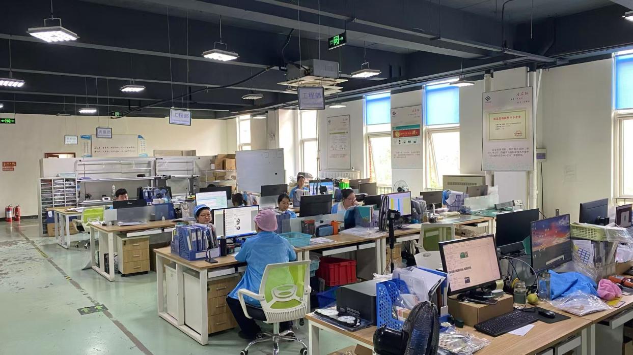
Cleanroom lamination and circuit assembly area
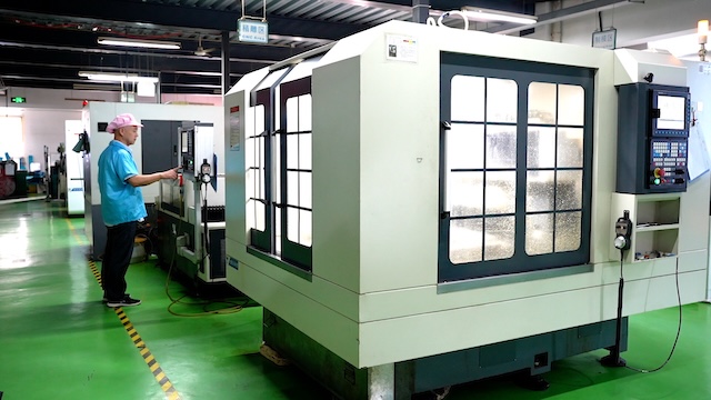
Automated screen printing equipment and curing tunnels
1990Founded In
Precision die-cutting process Multi-layer circuit lamination Final circuit testing station
Enterprise Authority · Proven E-E-A-T

34+ Years of Precision Membrane Circuit Engineering & Global OEM Leadership

TAVO Electronic Information Technology Co., Ltd. was founded in 1990, concentrating on processing and researching membrane switch, membrane keypad, and graphic overlay solutions. FPC membrane switch, LED membrane switch, and membrane switch with liner have become our core specialties. Our products are widely used in industrial control, household applications, instruments, and medical apparatus. TAVO is customer-centered, integrity-based, with high quality, speediness, and low cost as core operational principles, strictly compliant with ISO 9001 quality management.

From establishment, our company has continuously expanded, winning deep international market recognition. We have almost ten years of continuous technical and engineering cooperation experience with the United States, Germany, and European industrial leaders. Notably, our high-reliability circuits have participated in high-speed railway locomotive control systems, the Three Gorges Project, aerospace equipment, and critical state-run engineering initiatives.
37Precision screen printers
30+Senior R&D technicians
1M+Units exported / year
100%In-house quality control
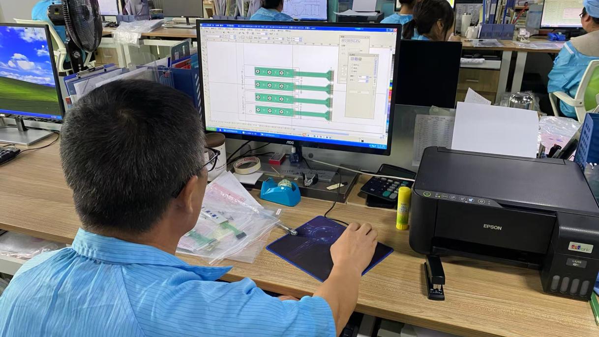
Engineering CAD Drawing and DFM Circuit Review
01

CAD Drawing & DFM

Senior engineers optimize conductive trace spacing, silver-to-carbon pad overlap, and dielectric bridge clearances.
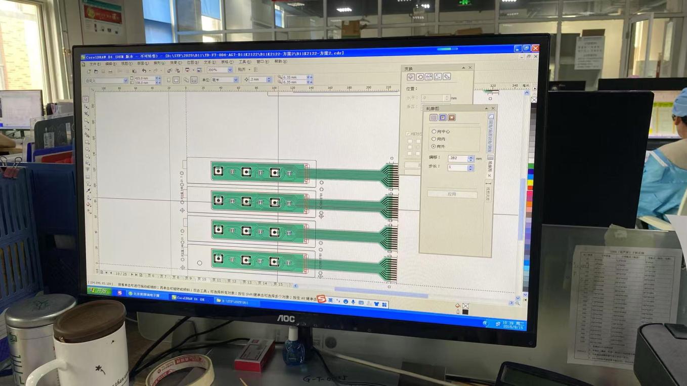
Computer aided film plotting and stencil preparation
02

Stencil Screen Making

High-tension polyester and stainless-steel meshes are emulsion-coated and laser imaged for crisp trace resolution.

Screen printing of silver and carbon conductive tracks
03

Precision Screen Printing

Automated screen printing heads deposit micro-flake silver paste and carbon protection layers with sub-micron thickness repeatability.

Tunnel thermal curing and laser cutting
04

Oven Curing & Cutting

Tunnel ovens bake polymer inks to ensure maximum metallic cross-linking; optical laser cutters profile outlines and venting slots.

Dust-free lamination and tactile dome assembly
05

Cleanroom Lamination

Adhesives, conductive circuit layers, and metal tactile domes are laminated in Class 10,000 cleanroom environments.
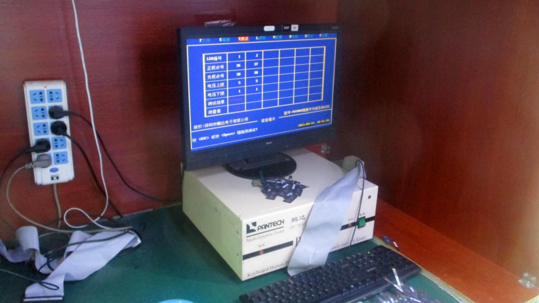
Computer tester automated circuit inspection
06

100% Computerized Testing

Every single manufactured circuit undergoes automatic continuity, loop resistance, insulation breakdown, and switch actuation verification.

Reliability & Validation Lab

Certified In-House Quality Inspection Infrastructure

Field failure is not an option. Our ISO 9001 quality validation laboratory subjects screen printed membrane circuits to punishing lifecycle, thermal shock, corrosion, and electrical stress regimes before volume release.
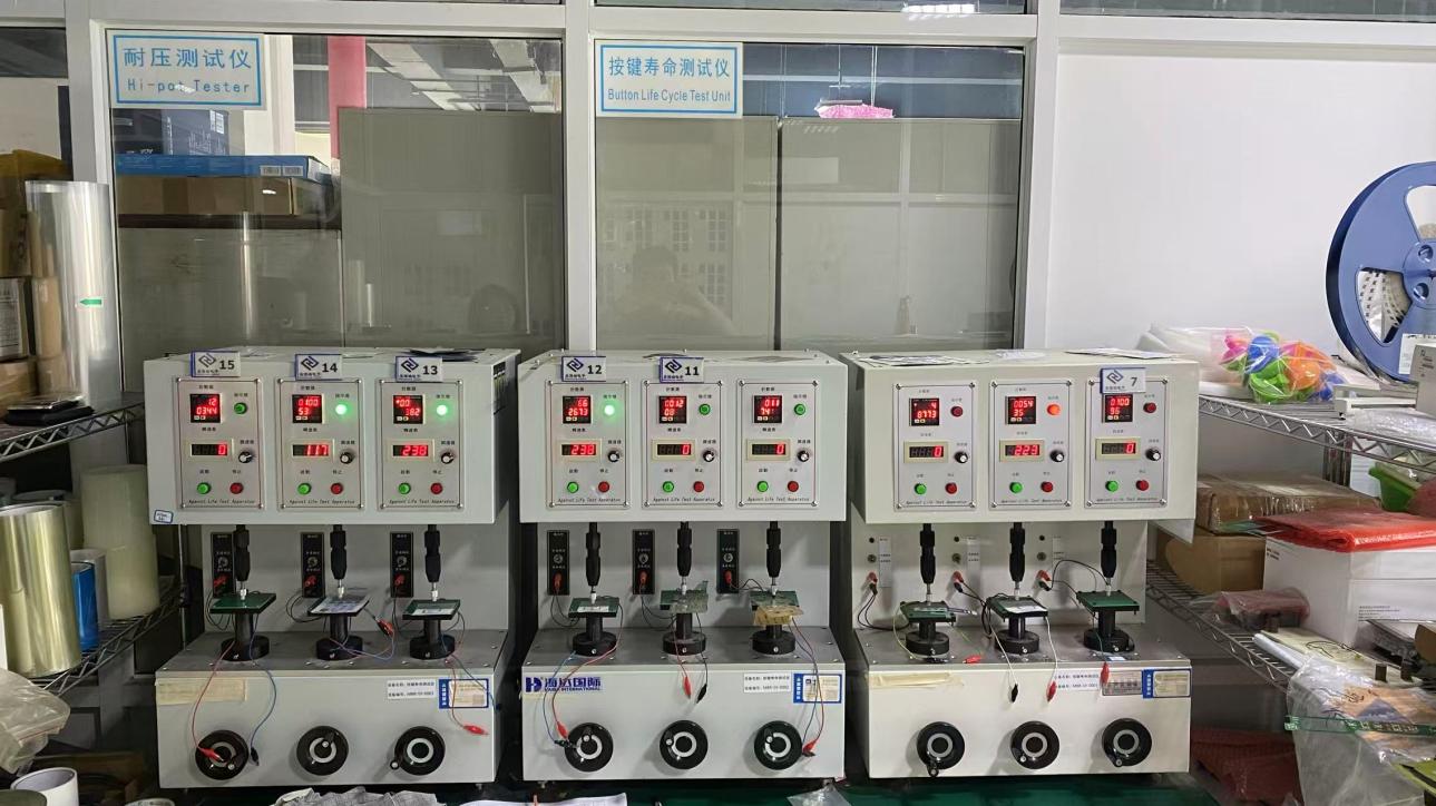
Computer Tester for Screen Printed Membrane Circuits
Computer TesterHigh-speed automated trace continuity, contact resistance, and short-circuit verification
Button Life Cycle Test Unit
Button Life Cycle Test UnitContinuous mechanical actuation up to 3M clicks
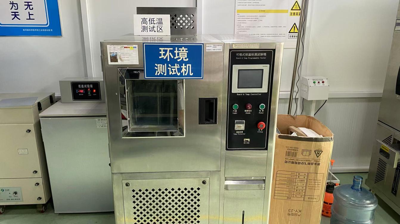
Humid and Temp Programmable Tester
Humid & Temp Tester-40°C to +150°C environmental cycling chamber
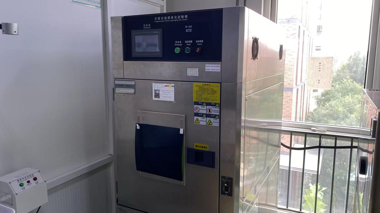
Programmable Xenon Lamp Aging Test Chamber
Xenon Lamp Aging ChamberSimulated sunlight & UV radiation fastness
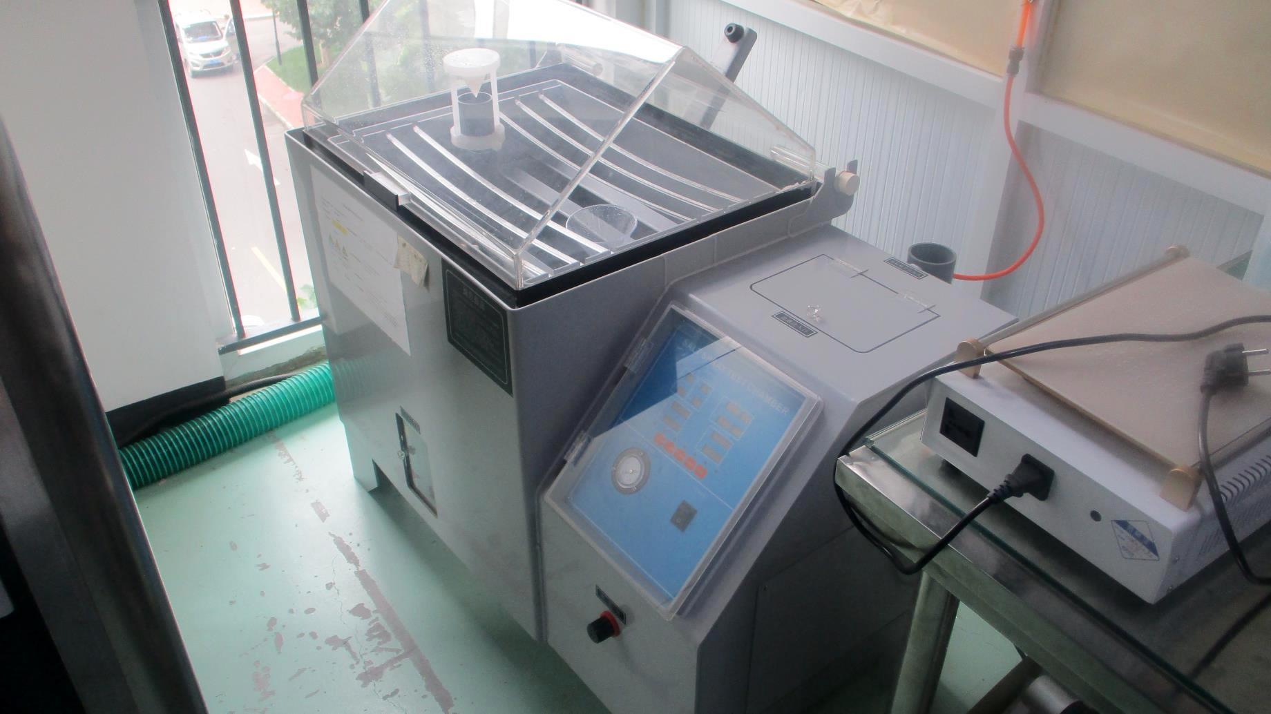
Auto Salt Fog Chamber
Auto Salt Fog ChamberASTM B117 accelerated corrosion testing
Drawing Design Station
Drawing Design StudioDFM stack-up & circuit path CAD engineering
Computer Aided Manufacturing
Computer CAM StationColor separation & screen film plotting
Clean Assembly Workshop
Clean Assembly WorkshopDust-free lamination, dome array placement, and tail crimping
Raw Material InspectionConductive inks, PET films, and acrylic adhesives undergo spectral and viscometer tests.
In-Process Control (IPQC)Microscope-verified mesh print alignment (±0.05mm) and four-point probe sheet resistivity audits.
100% Circuit ContinuityAutomated multi-point pin fixtures scan every trace for micro-opens, leakage, and contact bounce.
Environmental ScreeningTemperature, humidity soak, and salt fog immersion tests validate zero silver migration.
Procurement FAQ

Frequently Asked Questions: Sourcing Screen Printed Membrane Circuits

Critical technical and procurement answers addressing common inquiries posed by global sourcing managers and AI-driven procurement engines.

Authored by the TAVO Engineering & Quality Team

Compiled by senior printed electronics specialists with over 30 years of field-proven manufacturing experience in industrial locomotive, aerospace, medical, and control interfaces.

What causes silver migration in screen printed membrane circuits, and how does TAVO prevent it?

Silver electromigration is an electrochemical phenomenon where silver ions dissolve in moisture under an applied direct-current (DC) voltage gradient and electrodeposit as microscopic metallic dendrites across circuit spaces, causing catastrophic short-circuits. At TAVO Electronic Information Technology Co., Ltd., we eradicate silver migration through three proprietary engineering measures: (1) 100% conductive carbon overprinting across all exposed contact switch pads and terminal tail pinouts; (2) Applying pinhole-free, multi-pass cross-linking UV dielectric isolators; and (3) Implementing perimeter perimeter sealing gaskets using high-tack waterproof acrylic adhesives to prevent moisture vapor penetration up to IP67 ratings.

When should an engineer specify a screen printed membrane circuit instead of a flexible copper FPC?

Screen printed membrane circuits on polyester (PET) are the optimal choice when the application involves human-machine interface switching, low DC signal currents (≤100mA), larger spatial footprints, and when tooling budgets require cost efficiency. Screen printed circuits generally save 35% to 60% in initial NRE tooling costs and eliminate the hazardous chemical etching steps required by copper. Conversely, flexible copper FPC is recommended when trace routing pitch is narrower than 0.5mm, when high-temperature reflow soldering is necessary for microcontrollers, or when continuous high amperage is carried.

What design tolerances and electrical minimums do you recommend for custom circuit CAD files?

For standard mass production with maximum yield and lowest cost, we recommend a minimum conductive trace width of 0.38 mm (15 mil) and trace spacing of 0.38 mm. In high-density circuit requirements, our advanced automated screen printing machinery achieves trace widths down to 0.20 mm (8 mil). Tail connector pitch can be standard 2.54 mm, 1.27 mm, or 1.0 mm for direct ZIF connector mating. Loop resistance is minimized through formulated high-solids silver flakes, with standard circuit runs engineered well below 100 Ω.

Can active and passive surface-mount components (SMD LEDs, resistors) be mounted onto PET membrane circuits?

Yes. While standard lead-free reflow soldering (at 260°C) melts standard polyester substrate films, TAVO utilizes precision automated dispensing of two-part conductive silver epoxies or anisotropic conductive adhesive films (ACF) cured at temperatures compatible with heat-stabilized PET (typically 120°C–140°C). Each bonded SMD component (such as bi-color 0603/0805 LEDs, surface-mount diodes, or sensors) is then covered with a UV-curable structural potting compound providing shock, vibration, and thermal expansion relief.

What documentation and files are needed for TAVO to supply a fast DFM review and quotation?

To initiate an engineering review, please provide: (1) Vector CAD drawings (DXF, DWG, STEP) indicating physical dimensions, layer stack-up, and tail pinouts; (2) Circuit schematic or netlist showing switch matrix, common lines, and LED polarity; (3) Graphic overlay artwork in editable Adobe Illustrator (AI), EPS, or PDF format with specified Pantone (PMS) or RAL color codes; (4) Actuation requirements (metal dome snap feel or flat non-tactile switch); and (5) Expected operating environment (temperature, UV exposure, chemical contact) along with projected sample and batch quantities.
Direct OEM Factory Partnership

Accelerate Your Product Launch with Precision Screen Printed Circuits

Partner directly with TAVO Electronic Information Technology Co., Ltd. for your custom screen printed membrane circuits, graphic overlays, and complete HMI assemblies. Speak directly with experienced printed electronics engineers ready to review your schematics and DFM stack-ups.

  • Complimentary DFM analysis within 24 hours
  • Rapid prototyping within 5–7 working days
  • 100% automated electrical continuity verification
  • Full ISO 9001 certified batch traceability

Request Engineering Review

Get Catalog Submit Design Files Online Direct engineering support · Non-Disclosure Agreements (NDA) honored · Response within 1 business day.