A Metal Backer Membrane Switch combines a printed circuit layer, graphic overlay, and rigid metal support. That support can help the switch stay flat during installation and repeated use. It may also provide a firmer mounting surface than a flexible construction alone. For equipment panels, control stations, and compact instruments, these details can affect alignment, key feel, and long-term performance. Small differences matter.
The right backer depends on the enclosure, mounting method, operating environment, and expected force at each key. Aluminum can offer a lightweight support option, while stainless steel may suit designs that need greater rigidity. Actual results depend on thickness, cutouts, adhesive choice, and the complete switch stack-up. A metal layer does not automatically make a switch waterproof, more durable, or easier to operate; those outcomes require suitable design and testing.
This guide looks at why designers choose a metal-backed construction, what trade-offs to consider, and how material selection affects installation and use. It also points to practical checks, such as confirming panel flatness and testing key response in the finished assembly. A detail can be missed. Even a well-specified backer may not solve a poor enclosure fit, so prototypes and application-specific evaluation remain important.
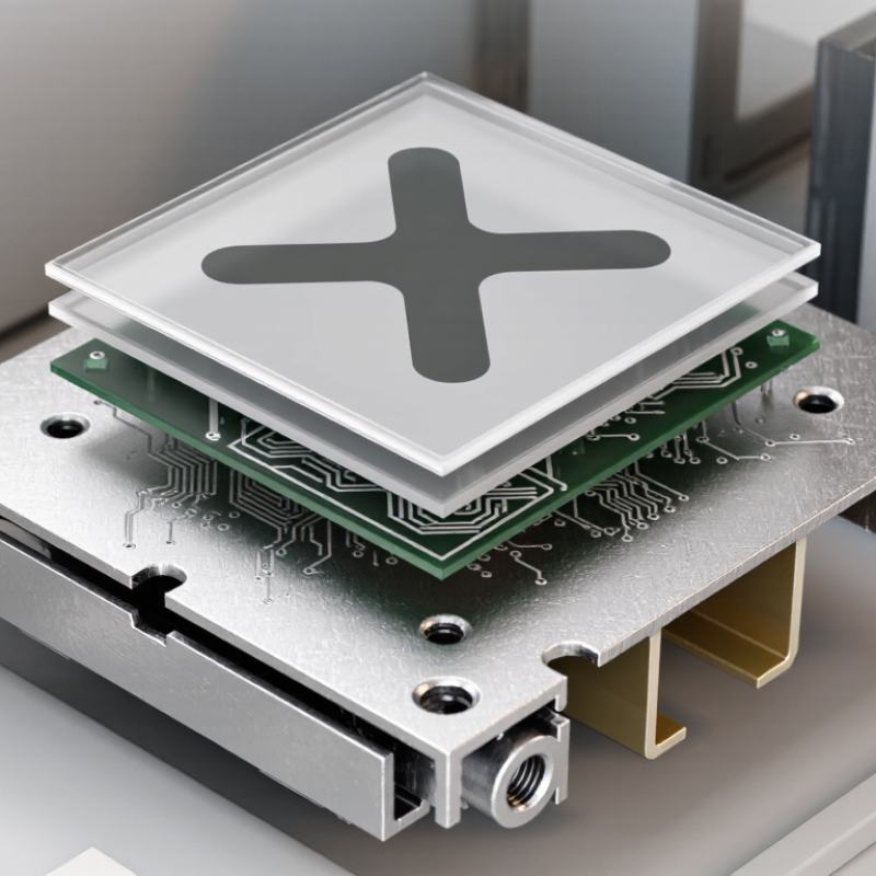
What Is a Metal Backer Membrane Switch?
A metal backer membrane switch is a low-profile control panel built from flexible electrical layers attached to a rigid metal support. The stack usually includes a printed graphic overlay, spacer, conductive circuit, and adhesive. Pressing a marked key brings circuit contacts together and registers an input. The metal plate sits behind these layers; it is not the key surface itself.
Backers are commonly made from aluminum or stainless steel, with the choice depending on weight, stiffness, and the environment. The plate helps the panel resist bending when a person presses a small key, and it can provide mounting points for screws or locating features. That matters when the switch must sit evenly against a machine housing. Small details count.
Designers should check the full stack thickness, adhesive compatibility, and clearance around mounting holes. A rigid backer may improve support, but it can add weight and limit how the panel bends around a curved enclosure. I would not assume that thicker metal always means a better switch. Test the assembly in its intended housing, then check key feel and alignment across the panel. A sample may look right on a bench, yet feel different once installed.
Why Choose a Metal Backer Membrane Switch?
How Its Layers and Components Work
A metal backer membrane switch is a compact stack, not just a printed button. At the top, a graphic overlay carries labels and protects the surface. Beneath it, a spacer creates a small air gap. Pressing the overlay closes the circuit between conductive layers, sending a signal to the device. A rear adhesive layer fixes the assembly in place, while the metal backer supports it against bending and uneven pressure. You can feel the difference: the key area stays steadier under a fingertip. But the backer is not magic; poor mounting can still cause flex or misalignment.
Material choices shape performance. Stainless steel offers corrosion resistance, while aluminum can reduce weight. The circuit may use printed silver ink or a flexible copper layer, depending on electrical and durability needs. IEC 60529 defines ingress-protection tests; for example, IPX7 testing involves temporary immersion in water up to 1 meter for 30 minutes. That rating applies only to a tested, assembled product, not to a membrane switch by default. Designers should also check actuation force, adhesive compatibility, and temperature exposure. Small details matter. A graphic that looks crisp on screen may become hard to read under glare, so prototype testing remains essential.
| Layer or Component | Typical Position | Common Construction | How It Works | Design Considerations |
|---|---|---|---|---|
| Graphic overlay | Top surface | Printed polyester or polycarbonate film | Displays labels, symbols, and operating instructions while protecting the switch surface. | Material, surface finish, printing method, and environmental exposure affect appearance and durability. |
| Overlay adhesive | Below the graphic overlay | Pressure-sensitive adhesive, selected for the overlay and application surface | Bonds the overlay to the circuit or spacer assembly. | Adhesive compatibility, temperature range, surface preparation, and edge sealing should be considered. |
| Upper circuit layer | Below the overlay or spacer | Flexible polyester film with printed conductive traces and contact areas | Provides one side of the electrical contact. Pressing a key can bring its contact area toward the corresponding lower contact. | Trace layout, contact geometry, and the flexibility of the film influence electrical routing and actuation. |
| Spacer layer | Between circuit layers | Die-cut insulating film with openings at switch locations | Keeps contacts apart when the key is released. An opening allows the upper contact to deflect and meet the lower contact when pressed. | Opening size and alignment affect travel, actuation feel, and reliable contact closure. |
| Lower circuit layer | Below the spacer | Flexible polyester film carrying conductive traces and mating contacts | Completes the circuit when a pressed key brings its contact together with the matching contact on the upper circuit. | Routing and contact design must match the intended electrical interface and switch layout. |
| Tactile dome (optional) | At selected key locations | Formed metal dome placed over a circuit contact | Can provide a noticeable tactile snap and help return the key after release. Not every membrane switch uses a dome. | Dome shape and operating force affect the feel of the key; placement must align with the contact and overlay artwork. |
| Circuit adhesive | Between circuit or spacer assembly layers, as required | Thin adhesive films with openings or patterns suited to the stack-up | Holds the functional layers together without blocking the intended contact areas. | Adhesive patterns must preserve switch openings and account for alignment and assembly tolerances. |
| Metal backer | Rear of the switch assembly | Typically a formed or flat sheet of stainless steel or aluminum | Supports the flexible switch stack and can provide a more rigid mounting surface than the films alone. | Material, thickness, flatness, mounting features, and corrosion requirements depend on the product and installation. |
| Mounting features | On or around the backer | Application-specific holes, cutouts, or formed features | Help locate and secure the assembly in its enclosure or control panel. | Feature positions should match the enclosure and avoid interfering with circuits, connectors, or moving parts. |
| Electrical tail and connector | Extends from the circuit layers | Flexible printed-circuit tail with exposed contact fingers for a compatible connector | Carries switch signals from the circuit traces to the host electronics. | Connector type, contact layout, tail length, and bend path must suit the host device and assembly space. |
| Complete switching action | Across the assembled stack | Overlay, circuit layers, spacer, optional tactile elements, and supporting backer | A key press deflects the overlay and circuit structure; the electrical contacts close, and they separate again when pressure is removed. | Layer choices and geometry are application-specific. A metal backer adds support, but does not by itself determine electrical performance or tactile feel. |
| Construction varies by design. Materials, layer order, adhesives, tactile elements, and backer details should be confirmed against the requirements of the intended application. | ||||
A metal backer gives a membrane switch a firm, flat foundation. That support can limit flex when users press near an edge or when the panel is fastened into an enclosure. A steadier mounting surface may also help keep key feel consistent across the keypad. A firm base matters.
The material choice affects stiffness and weight. ASM International’s materials references put typical elastic modulus near 69 GPa for aluminum and 200 GPa for steel; actual values vary by alloy and thickness. In practice, steel can resist bending more strongly, while aluminum offers lower mass. The backer can also spread localized pressure from clips or fasteners. Still, metal is not automatically the better choice. It may add weight, conduct heat, or need protection against corrosion, depending on the environment. I would check the complete assembly, not just the sheet: switch layers, adhesive, cutouts, and mounting torque all matter. A thin panel can flex despite a metal backer, so prototype testing under real operating conditions is worth the extra step.
Typical Young’s Modulus of Common Backer Materials
Stainless steel and aluminum have a much higher Young’s modulus than common polymer films, so a metal backer can provide a more rigid support surface and help a membrane switch maintain its shape. Values shown are approximate typical material values; actual properties vary by grade and construction.
Metal backer membrane switches are useful where a thin control panel needs firm support. In factory equipment, operators may press buttons repeatedly while wearing gloves. A metal backing plate helps keep the panel stable against the machine housing. It can also support tactile metal domes, giving a more defined click than a soft, unsupported surface.
They are also found on diagnostic instruments, laboratory devices, and some medical equipment. These panels often sit beside displays or small controls, where a flat mounting surface matters. In vehicles and outdoor machinery, a rigid backer can help the switch assembly resist flexing during vibration. The full design still matters: sealing, connector placement, and the enclosure determine how well a panel handles moisture or cleaning.
Not every application needs metal. A backer adds weight and may increase cost, while poorly selected materials or finishes can create corrosion concerns in damp environments. Measure the available depth, expected press force, and mounting method before choosing one. Test a physical sample. It may reveal an awkward button feel or a panel that sits unevenly—details that drawings can miss.
Choose a membrane switch by studying its real operating environment, not just its appearance. A metal backer can add stiffness to a large control panel and help keep keys aligned during repeated presses. It may be unnecessary on a small, well-supported housing. Check the available mounting depth, panel flatness, key spacing, and whether operators wear gloves. A raised key can be easier to locate by touch, but it may collect dust around its edge. Small details matter.
Specify environmental performance for the complete assembly. IEC 60529 defines IP67 as dust-tight and suitable for temporary immersion up to 1 metre for 30 minutes; that rating does not automatically cover water jets. Ask for test evidence on the switch, adhesive, tail, and enclosure together. For static discharge, IEC 61000-4-2 includes test levels up to 8 kV contact and 15 kV air discharge. Match the required level to the installation and nearby equipment. Then test actual actuation force, feedback, and cycle life under realistic use. A laboratory result helps, but it cannot reproduce every operator or cleaning routine. That gap is easy to overlook.
It is a thin control panel with flexible electrical layers attached to a rigid metal plate. The plate supports the panel from behind.
The overlay moves slightly, closing contacts in the circuit layers. The device then receives an input. A small click may not occur.
A typical stack has a printed overlay, spacer, conductive circuit, adhesive, and metal backer. Each layer has a job.
It can reduce bending when a fingertip presses near an edge. The keypad may feel steadier against a flat housing.
Aluminum is lighter, while stainless steel can offer greater stiffness and corrosion resistance. The right choice depends on weight, thickness, and surroundings.
No. Water resistance depends on the complete, tested assembly, including seals and mounting. Don’t assume the backer keeps water out.
Check the full stack thickness, adhesive fit, mounting-hole clearance, and key alignment. Test it in the actual housing.
Not always. It may add weight or limit bending around a curved enclosure. A bench sample can feel different once installed.
Check actuation force and mounting pressure across several keys. Clips, fasteners, and uneven surfaces can change the feel. Small differences matter.
A Metal Backer Membrane Switch combines a printed circuit and flexible membrane layers with a rigid metal support plate. Each layer has a distinct role: the graphic surface provides clear controls, the circuit layers register input, and the metal backer supports the assembly. Together, these components create a compact interface designed for dependable operation.
The metal backing can improve rigidity, stability, and resistance to bending, while also helping the switch maintain consistent performance when mounted in equipment. These switches may suit industrial controls, medical equipment, appliances, and other devices that need a durable, low-profile interface. Choosing the right design depends on factors such as the operating environment, required key layout, mounting method, expected use, and desired tactile response. Matching these needs to the switch’s materials and construction helps ensure it fits the application.