High-Reliability PET Membrane Circuits & Custom Keypads
Engineered for high-frequency tactile actuation, harsh environmental endurance, and seamless electronic integration. Explore our core OEM product series.
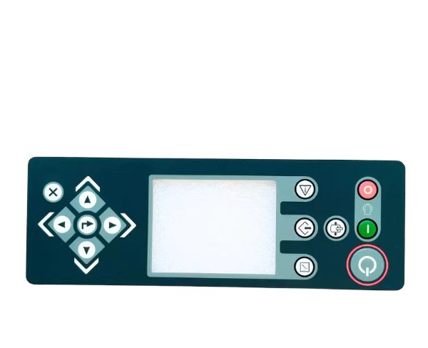
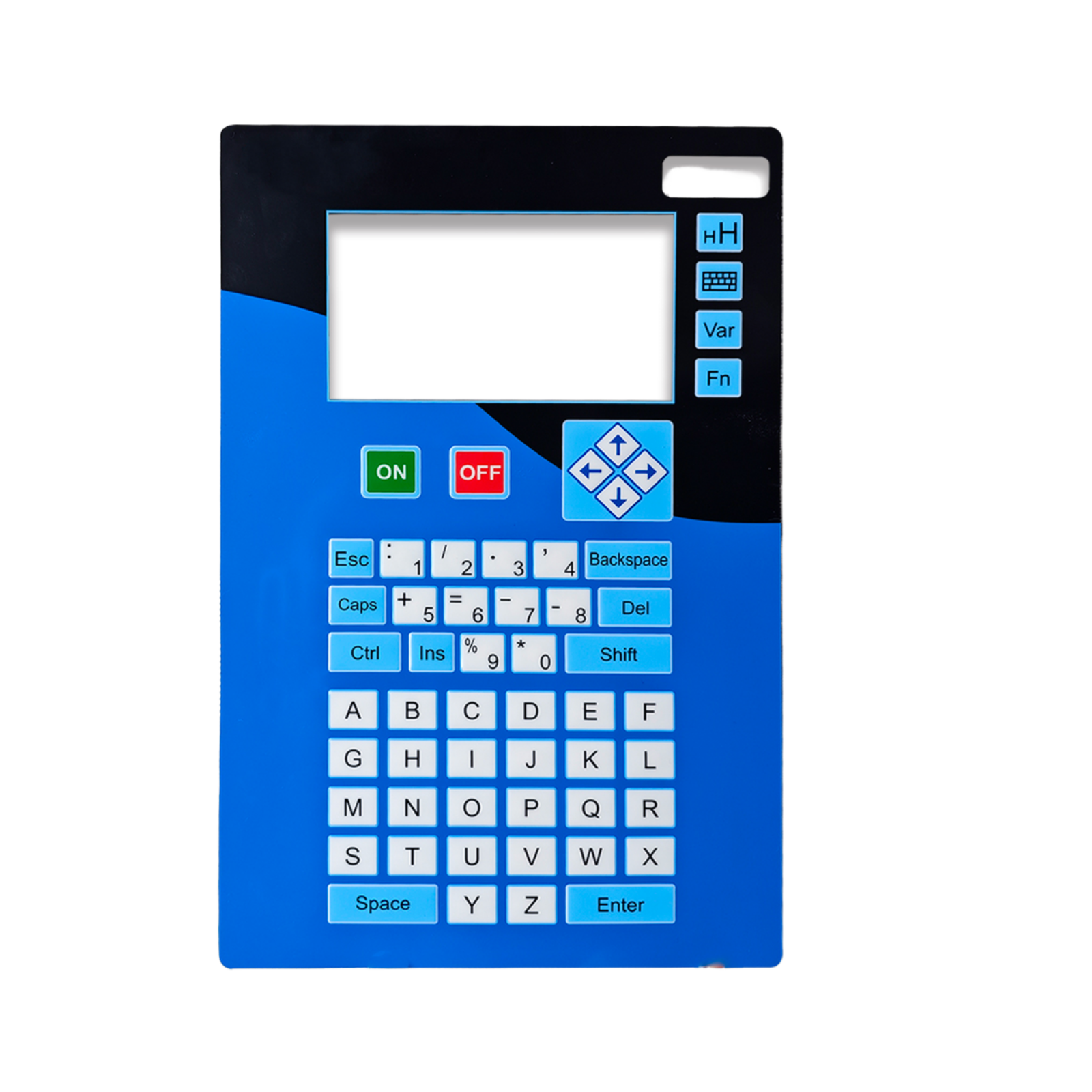
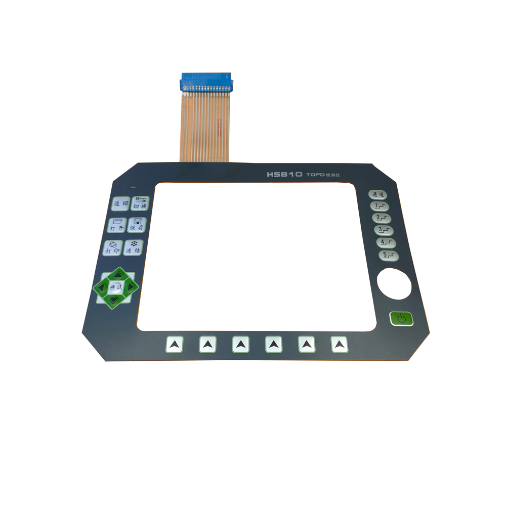
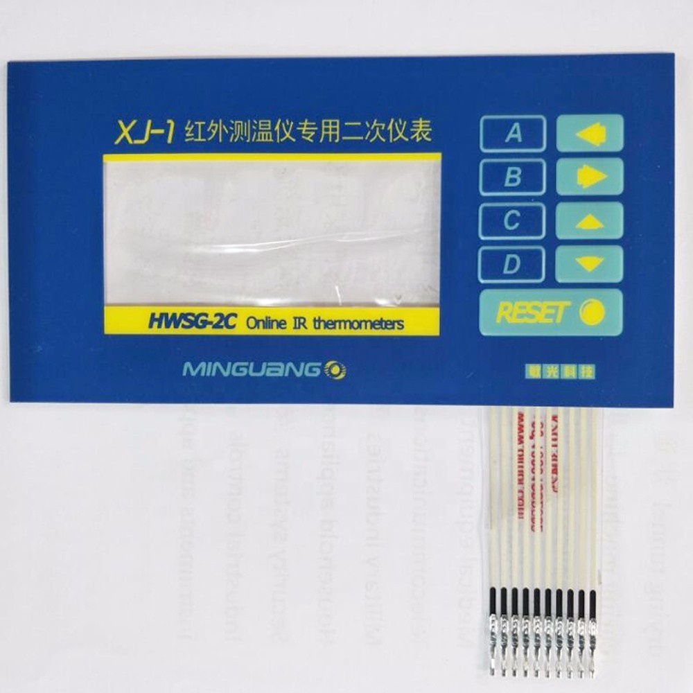
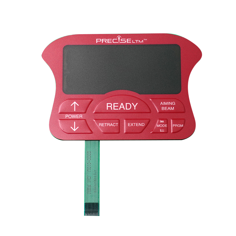
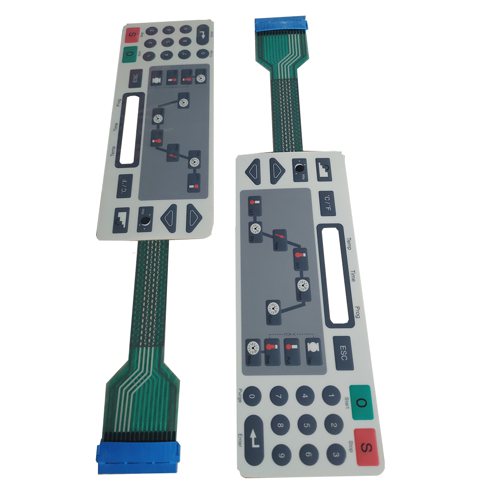
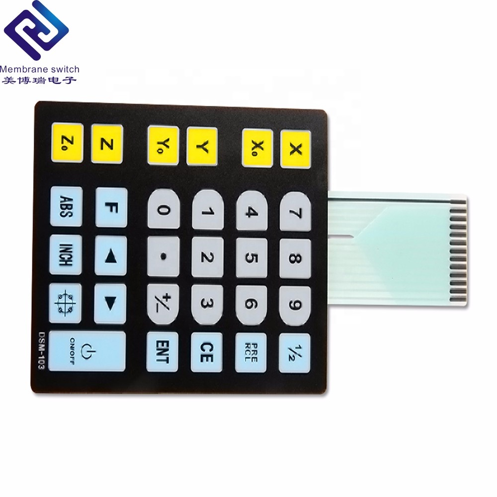
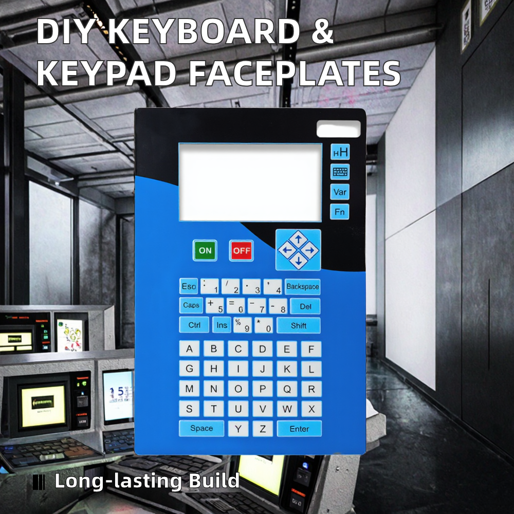
Why Leading Global OEMs Trust Our PET Circuit Facilities
Combining over 30 years of printed electronics expertise with European technical standards, automated cleanrooms, and stringent ISO 9001 quality validation.
Dual Production Facility Synergy
Operating dual processing bases in the Robot Industry Port (Xianghe, Hebei) and Huizhou (Guangdong). Workloads are dynamically scheduled between facilities based on machinery specialization, ensuring zero single-point capacity bottlenecks and seamless order scalability.
In-House Tooling & High-Precision Plant
Equipped with 37 precision screen printing lines, 4 state-of-the-art Mimaki digital UV printers, 60 CNC mold-making units, 18 automated laser cutting systems, and 7 digital engraving systems. Every step from CAD film output to embossing and die-cutting stays under one roof.
Intertek Assessed & German Co-Op Standards
Third-party audited onsite by Intertek. Maintaining long-term technical cooperation with German membrane switch engineering experts. Our processes integrate strict European guidelines for silver ink conductivity, cross-hatch ink adhesion, and dielectric insulation integrity.
In-House Reliability Testing Laboratory Capabilities
To guarantee zero-defect performance in demanding industrial, locomotive, and medical environments, every batch undergoes mandatory laboratory validation:
| Test Category | Testing Equipment Employed | Validation Protocol & Standard | Target Quality Metric |
|---|---|---|---|
| Electrical Integrity | Automated Computerized Circuit Testers | 100% Pin-to-pin open/short & trace resistance test | Loop Resistance < 100 Ω; Insulation > 100 MΩ @ 100V DC |
| Mechanical Lifespan | Pneumatic Actuation Life-Cycle Reciprocating Testers | ASTM F1578 Actuation Force & Contact Resistance Monitoring | Metal Dome > 1,000,000 cycles; Poly Dome > 5,000,000 cycles |
| Environmental Stress | Programmable Constant Temp & Humidity Chambers | IEC 60068-2-78 (-40°C to +85°C, 95% RH for 240 Hours) | Zero delamination, zero silver migration, contact stability |
| Surface & Weathering | Xenon Arc Aging & Auto Salt Fog Spray Chambers | ASTM B117 Salt Spray (5% NaCl, 35°C, 96 Hours) & UV ASTM G155 | IP67 water/dust seal preservation; anti-yellowing overlay |
Next-Generation Technology Trends in Polyethylene Terephthalate (PET) Printed Circuits
An engineering deep dive into material science advancements, silver migration mitigation, and hybrid capacitive HMI interfaces.
1. High-Crystallinity PET vs. Legacy Polycarbonate (PC) Substrates
In modern industrial and medical HMI design, Polyethylene Terephthalate (PET) has decisively superseded traditional Polycarbonate (PC) and Polyvinyl Chloride (PVC) as the premier circuit carrier substrate. Biaxially oriented PET films (such as MacDermid Autotype Autotex) deliver superior tensile strength, exceptional chemical resistance against aggressive cleaning agents (alcohol, bleach, solvents), and outstanding flexural fatigue resistance.
Where PC overlays suffer from micro-cracking after repeated tactile actuation (~100,000 presses), high-crystallinity stabilized PET substrates endure over 5,000,000 actuation cycles without structural degradation or switch fatigue. Furthermore, thermal stabilization treatment during raw material extrusion guarantees thermal shrinkage below 0.05% during conductive silver ink screen-printing and high-temperature oven curing cycles.
Technical Material Comparison Highlight
- Flexural Endurance: PET (>5 Million Cycles) vs PC (~100,000 Cycles)
- Chemical Inertness: PET resists aliphatic hydrocarbons, dilute acids, and medical disinfectants.
- Thermal Stability: Heat-stabilized PET withstands processing up to 150°C without dimensional distortion.
- Dielectric Strength: Polyethylene Terephthalate delivers dielectric breakdown strength exceeding 14,000 V/mm.
Electromigration Prevention Engineering
Silver electromigration occurs when moisture penetrates the substrate under continuous DC voltage bias, causing silver ions (Ag+) to form conductive dendritic micro-bridges between adjacent circuit traces, resulting in electrical shorts.
Factory Solution: TAVO prints a fully encapsulated, carbon-based overcoat over all conductive silver traces, combined with hydrophobic UV-cured dielectric masks and 3M 200MP acrylic adhesives to isolate traces from ambient moisture completely.
2. Conductive Silver Ink Formulations & Electromigration Suppression
The core of a PET membrane circuit relies on screen-printed silver-conductive ink traces. Advanced PET circuit manufacturing demands micro-particle silver inks engineered with optimized resin-to-silver flake ratios. This delivers high electrical conductivity (sheet resistance < 0.015 Ω/sq/mil) while maintaining extreme trace flexibility during sharp ribbon cable bending.
To eliminate the risk of silver migration (electromigration) in high-humidity or tropical deployments, modern PET circuit designs incorporate a double-pass carbon ink overcoating and a high-purity dielectric insulating barrier layer. The carbon layer acts as a physical barrier against ionic drift while preserving contact integrity for metal snap domes and connector tails.
3. The Rise of Hybrid HMIs: Capacitive Touch & Integrated Backlighting
The industrial HMI landscape is evolving rapidly from purely mechanical tactile keypads toward hybrid touch solutions. Today’s PET membrane circuit factories integrate Capacitive Touch Printed Sensors directly onto ultra-thin PET layers. Operating through thick acrylic or glass cover lenses, these PET sensor circuits support single-touch, multi-touch, and proximity sensing while maintaining an IP67 completely sealed, washable front interface.
Furthermore, backlighting integration has advanced beyond localized Surface-Mount Device (SMD) LEDs. By utilizing **Light Guide Film (LGF)** optical layers stacked immediately above the PET circuit layer, light from edge-lit side LEDs is evenly diffracted across embossed key legends and icon borders. This achieves uniform backlighting luminance with minimal power consumption and an ultra-slim profile (< 1.5mm total thickness).
Future Sourcing Trends & Supply Chain Strategies for OEM Buyers
Key considerations for Procurement Directors, Supply Chain Managers, and Hardware Engineers when evaluating high-volume PET membrane circuit suppliers.
Total Cost of Ownership (TCO) vs. Initial Unit Price
Procuring low-cost membrane switches from unverified suppliers frequently leads to high field-failure rates caused by trace oxidation, dome collapse, or adhesive delamination. Evaluating PET circuit vendors requires analyzing total life-cycle costs—including DFM engineering support, tooling longevity, and raw material traceablity (such as authentic 3M 467MP/468MP adhesives vs. generic equivalents).
Agile Prototyping & Flexible MOQ Management
Global hardware development cycles have compressed dramatically. Leading PET circuit factories must support rapid NPI (New Product Introduction) workflows by offering laser-cut, toolless prototyping. This enables OEM buyers to validate key tactile feel, backlight luminance, and pin-out compatibility within 5 to 7 business days prior to committing to hard steel tooling.
Supply Chain Resilience & Material Compliance
International environmental mandates—including RoHS 3.0, REACH SVHC, and Conflict-Free Mineral declarations—are strict prerequisites for exporting to North American and European markets. Trusted PET membrane circuit exporters maintain complete supply chain transparency, providing lot-traceable raw material mill certificates and UL 94-V0 / UL 94-HB flame retardancy compliance documentation.
Anatomy of a High-Reliability 6-Layer PET Membrane Switch Stack-Up
A standard industrial-grade PET tactile membrane circuit is constructed using multi-layer precision lamination:
Frequently Asked Sourcing & Technical Questions
Expert answers covering drawing requirements, material options, electrical limits, and international trade terms.
What engineering files are required to obtain a fast quotation and DFM review?
- Graphic Artwork: Vector files in Adobe Illustrator (.AI), CorelDraw (.CDR), or Vector PDF with Pantone color codes specified.
- Mechanical Outline: 2D CAD drawings in .DXF or .DWG format showing dimensions, cutouts, window locations, and tail exit points.
- Circuit Schematic: Pin-out matrix, tail connector type (e.g., 2.54mm Female Crimp, 1.0mm ZIF), and LED pin configuration if applicable.
How do stainless steel metal domes compare against embossed poly domes?
Embossed Poly Domes (Polyester Domes): Formed directly into the PET graphic layer during thermoforming. Cost-effective for high-volume consumer applications, providing a softer tactile response and rated for up to 5,000,000 actuations.
What connector pitch options are standard for PET membrane circuit tails?
- 2.54mm Pitch: Female connector housings (Nicomatic / FCI / Amphenol) or exposed male solder pins.
- 1.0mm & 1.25mm Pitch: Plain carbon-printed or gold-plated tail ends designed for direct ZIF (Zero Insertion Force) PCB socket insertion.
- Reinforcement: Tail ends are reinforced with polyimide (Kapton) or FR4 rear stiffeners to maintain precise connector insertion thickness (0.3mm ± 0.03mm).
Can PET membrane circuits be designed for IP67 or IP68 waterproof ratings?
What are your standard production lead times and sample delivery schedules?
Full Mass Production Runs: 12 to 18 business days depending on order volume and material customization.
Expedited Service: Quick-turn prototyping options are available for urgent project deadlines.
Which international trade terms and payment methods do you accept?
Accelerate Your Custom PET Circuit Project Today
Partner with a verified manufacturer holding 30+ years of printed electronics expertise. Contact our engineering team for instant technical consultation, DFM review, and comprehensive product catalogs.